

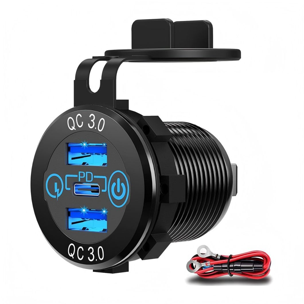
Overview of Battery Switch / Battery Valve
| Project | Key Points |
|---|---|
| Definition | A device designed to either sever or link the electrical pathway between the battery and the load when necessary, safeguarding against battery depletion, short circuits, or providing secure disengagement during maintenance or emergencies. |
| Working Principle | Generally, it operates as a switch that can be either electromagnetic or mechanical. When the switch is engaged, the internal connections link, permitting current to flow from the battery to the load; conversely, when it is disengaged, the connections part or the magnetically actuated valve opens, breaking the circuit to accomplish "power-off. " Control can be done manually through toggling, pressing buttons, or automatically via signal triggers such as low voltage or overcurrent safeguarding. |
| Main Types |
Integrated with traditional classifications of electrical switches |
| Typical Applications |
|
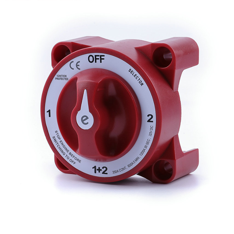
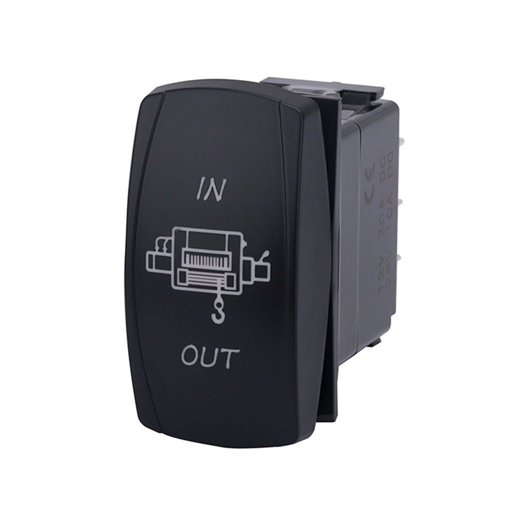
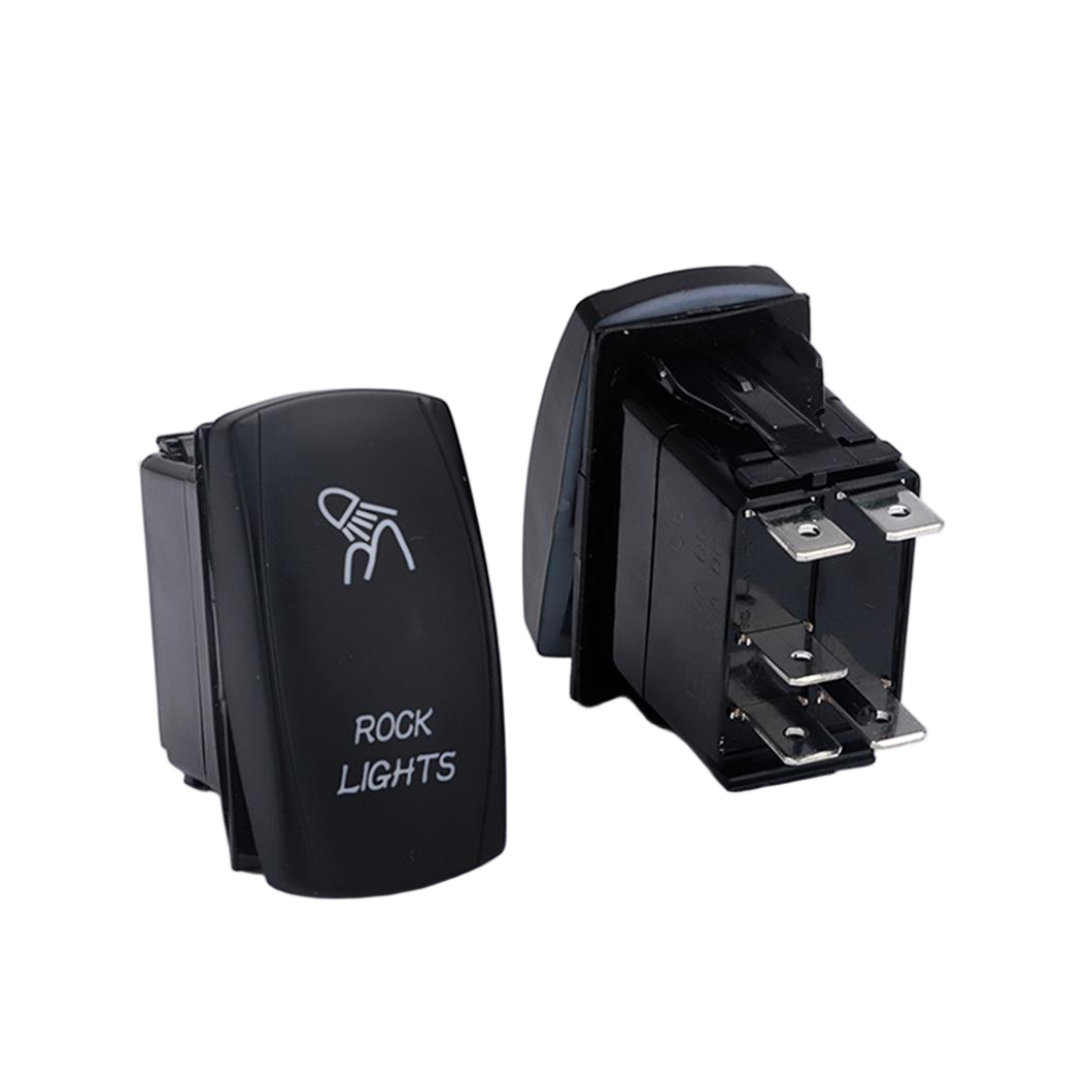
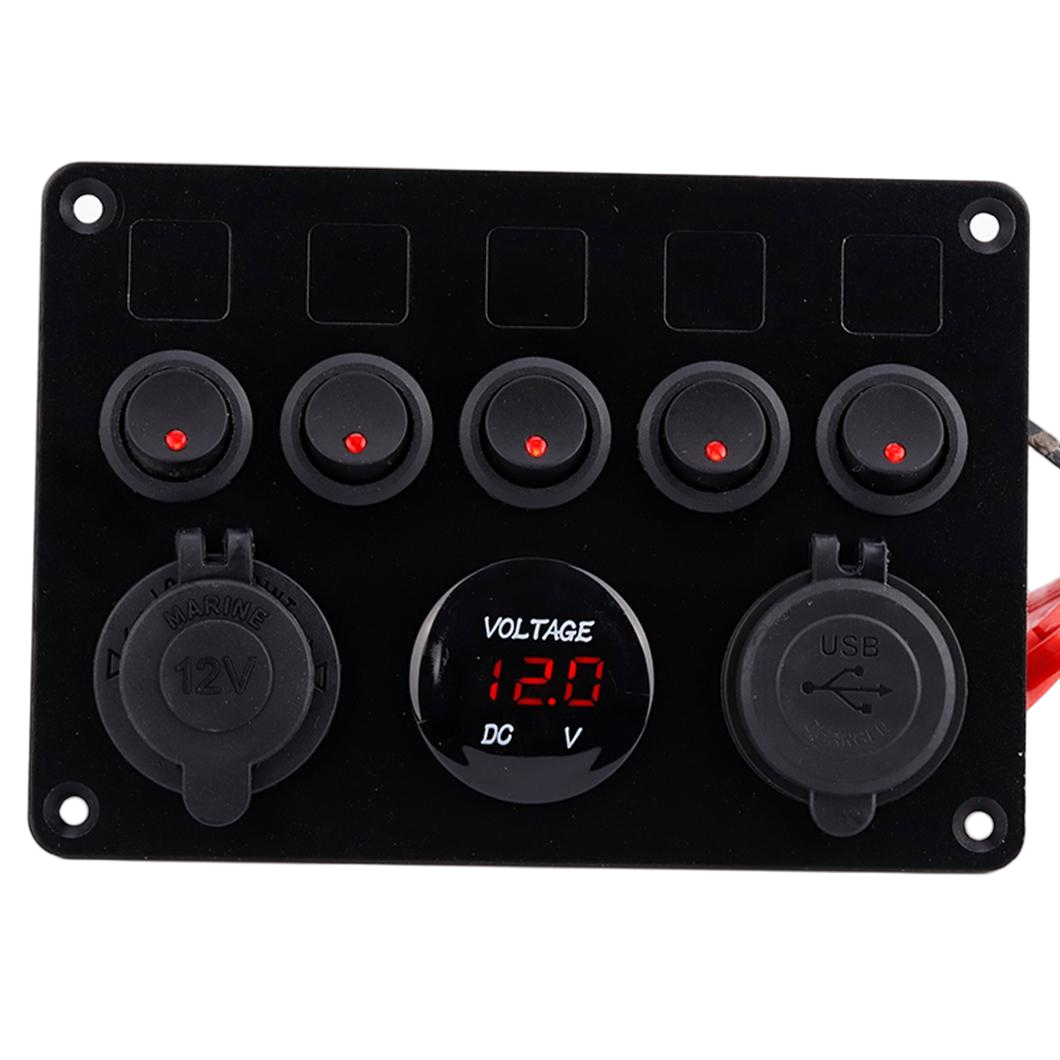
| Structure and Installation | - Dimensions: Typical panel mounting measures about 78 mm × 97 mm, with a rear mounting hole diameter of roughly 9. 2 mm (see a specific product catalog for details). Operation Position: Knobs or levers facilitate adjustments between various connection modes, such as:
Indicator Lights: Most designs feature status indicator lights to show whether the switch is open or closed. |
| Role in the Battery Pack | In a multi-cell series or parallel arrangement, each battery cell may come with its own switch (S₁, S₂... ), allowing:
|
| Selection Key Points |
- Voltage and Current Rating: Should surpass the highest operational voltage and peak discharge current of the system.
- Power Rating and Interrupting Capability: Confirm that it can effectively interrupt and endure surge currents in situations of short circuits or excessive current.
- Protection Classification: For use in outdoor or moist settings, suggest a rating of IP54 or better.
- Mode of Operation: Choose between manual or automatic (electromagnetic) based on site-specific needs.
- Compatibility of Dimensions: Ensure that the openings reserved in the panel or enclosure align with the switch dimensions.
|Safety and Maintenance |
- Pre-disconnection Inspection: Ensure that the load is halted and refrain from using the system while it is powered.
- Regularly assess contact wear: The mechanical contacts of switches may degrade over time and should be cleaned or replaced as required.
- Prevent erroneous operations: Implement locks to avoid unintentional actions or devices for double verification on vital systems like UPS.
- Document operations: Note the times when each switch is opened or closed in the maintenance log to facilitate troubleshooting.
Standard electrical safety guidelines (aligned with the usage instructions in [8])
|Common Misconception |
- The false belief that battery switches can serve as a substitute for fuses: switches can only interrupt the circuit either manually or automatically during normal use and do not offer protection against immediate overcurrent.
- There's an assumption that all battery switches possess backflow prevention features: only specialized anti-backflow valves are designed for this purpose, while standard mechanical valves will still allow current to flow in reverse.
Summary
The battery switch plays a crucial role in ensuring the safety and adaptability of battery systems. It enables the connection and disconnection of circuits using mechanical or electromagnetic methods, capable of operating under both manual and automatic controls. These switches find common use in UPS systems, marine applications, solar energy storage, automobiles, and other contexts. When choosing a switch, it is important to consider the rated voltage and current, breaking capacity, protection standards, and dimensions; during operation, adherence to safety protocols such as disconnecting power, inspecting contacts, and documenting actions is essential for the dependable functioning of the system.