
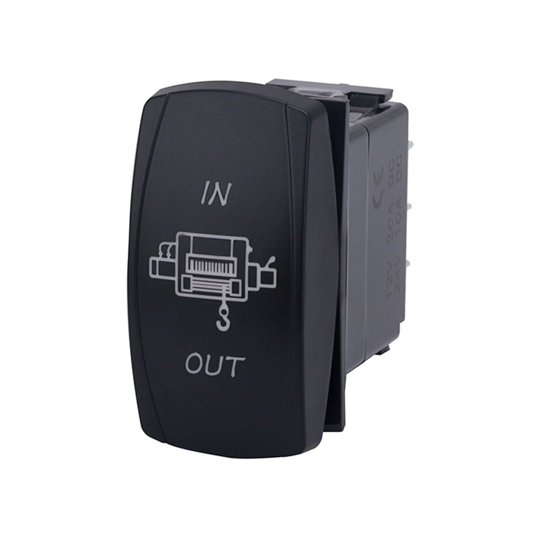
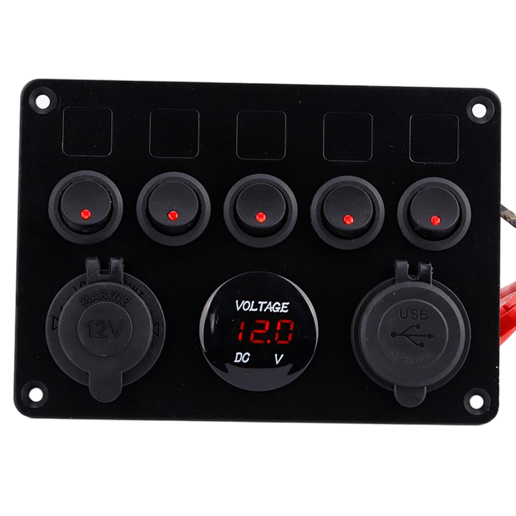
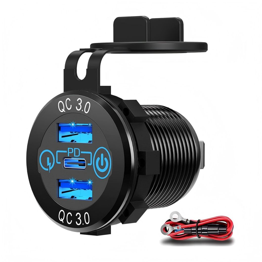
Wiring Methods, Precautions, and Instructions for Ship Type Switches
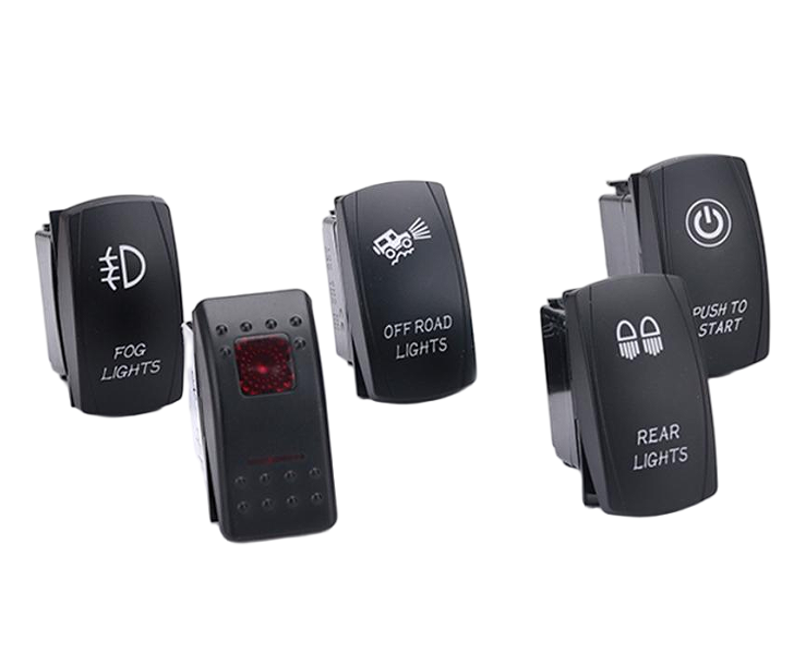
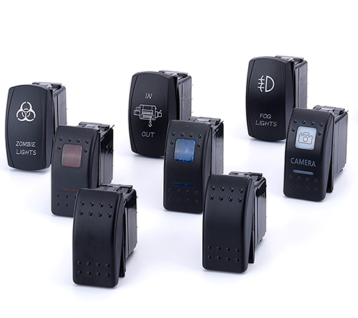
The structure of the boat shaped switch is the same as that of the toggle switch, except that the handle is replaced with a boat shaped one. Usually, a straight line and a circle are used on the Switch Panel to represent the on/off state of the power supply, and their meanings are derived from binary 1 and 0.
The "-" position represents the number "1", which means "on" and is equivalent to a level signal passing through;
The "O" position represents the number "0", which means "off" and is equivalent to a broken level signal;
The "-" and "O" are usually marked on both ends of the button of the ship type (rocker) switch. A more scientific design is to mark the "ON" word on the "-" end of the switch installation position and the "OFF" word on the "O" end.
Internal structure of ship type switch
The boat shaped switch has a metal plate inside and a spring pivot in the middle.
Connected to the spring is the moving contact point
The static contact is fixed at the bottom of the switch and connected to the pin
Pressing the rocker allows the moving and stationary contacts to come into contact or separate, thus achieving the on/off control of the circuit.
If the spring is displaced or the plastic bracket is aged and deformed, it will cause the switch to be unresponsive or even unable to connect or disconnect the circuit.
Some ship switches also come with Indicator Lights, usually using neon bulbs. Neon bubbles are gas discharge tubes that have a breakdown voltage, usually around DC70-90V (corresponding to an effective AC voltage of around 50V). They cannot be lit below this voltage. In addition, neon bubbles have a negative resistance effect after being lit up, so a resistor should be used to limit the current.
Main parameters of ship type switch
Rated working voltage and current:
The safe voltage and current allowed by the switch during normal operation. If the voltage value applied to both ends of the switch is greater than this value, it will cause ignition and breakdown between the two contacts. If the current exceeds the rated current, the contacts of the switch will burn out due to excessive current.
contact resistance
The resistance value between each pair of contacts when the switch is in the on state is generally required to be below 0.1-0.5 Ω, and the smaller the value, the better.
insulation resistance
The resistance value between the conductor and insulation parts of the switch, and the insulation resistance should be greater than 100M Ω.
lifespan
The number of times a switch can be operated under normal working conditions is generally required to be around 5000-35000 times.
When choosing a ship type switch, appropriate rated voltage and rated current parameters should be selected based on the power supply voltage and the maximum power of the electrical appliances controlled by the switch. Generally, the voltage of the electrical appliances should be within the rated voltage range of the ship type switch, and the current should be less than 80% of the rated working current of the ship type switch.
Classification of ship type switches
Ship type switches can be divided into the following types according to their structure:
Single pole single throw: 1 moving contact and 1 stationary contact, with only 1 channel;
Single pole double throw: 2 moving contacts and 2 stationary contacts (can connect the stationary contacts on both sides separately);
Double pole single throw: 2 moving contacts and 2 stationary contacts, with 2 channels;
Double knife double throw: 4 moving contacts and 4 stationary contacts, with 4 channels (can connect the 4 stationary contacts on both sides separately).
According to parameters and usage environment, it can be divided into:
1. Small capacity non sealed type
This type of ship type switch has a relatively low rated voltage and current, such as 5A @ 120VAC, 28VDC; 2A @ 250VAC, The material of such products is usually brass coated with gold or silver. Long lifespan, up to around 50000 cycles.
2. Large capacity sealed type
For large capacity ship type switches, they are more suitable for power control in special environments. Due to their sealed structure, they do not generate electrical sparks during operation, or the parts where electrical sparks are generated can be isolated from the outside by gas.
When installed in an environment with flammable dust or flammable gas, it will not ignite flammable dust or flammable gas due to electric sparks generated during work, ensuring safety.
Its rated current is usually relatively high, such as 15A @ 125VAC; 8A @ 250VAC, The terminal material is often brass coated with tin.
According to their shape, they can generally be divided into several types: square, circular, and elliptical.
The copper parts inside the ship type switch socket are crucial components for ensuring smooth current flow and reducing heat generation. High quality electronic switch power sockets are made of copper components with excellent performance: anti-oxidation, strong resistance, thick copper sheets, and minimal riveting, which are the four major indicators for the excellence of copper components in sockets.
1. Thick copper sheets can improve the current passing capacity and reduce the resistance of copper components themselves.
2. Strong durability, especially for the parts used in socket outlets, not easily deformed. Even if the socket is frequently plugged in and out for a long time, it can maintain appropriate clamping force, ensure a tight connection between the socket and the plug, and reduce arcing.
3. Antioxidant, non rusting, reduces resistance increase and heat generation caused by rusting.
4. Less riveting, preferably an integrated copper component, further reduces the risk of fracture and rivet heating caused by the interface.
In terms of material, brass has a bright yellow appearance, excellent conductivity, and a soft texture, but its wear resistance, oxidation resistance, and elasticity are not ideal. After long-term use, the surface of brass parts will be oxidized and corroded, the color will darken, and the touch resistance will increase; After repeated plugging and unplugging, brass plates often suffer from poor resistance and severe deformation, resulting in the inability to obtain electricity or arc due to poor touch, which cannot guarantee safe use of electricity.
Nowadays, mainstream sockets use tin phosphorus bronze as the material for copper components. The appearance of tin phosphorus bronze alloy is purple red, and its biggest feature is its high fatigue resistance, strong elasticity, excellent corrosion resistance, and oxidation resistance. Even after long-term use, its appearance will not be oxidized or corroded, and the sleeve will not deform, always maintaining a suitable clamping force.
Considering the thickness of the copper parts, if it is not possible to visually inspect the product by opening it, the method of weighing by hand can be used: the more copper parts are used, the heavier the weight of the socket.
Installation and wiring method of ship type switch
Ship type switches, like regular switches, serve to disconnect and connect circuits.
When installing, there are two open clips on both sides of the boat shaped switch. Align the switch with the holes on the board and push it downwards. Wait for the clips to fix the switch on the board.
When disassembling, simply press both fixing cards inward at the same time, and then gently push the switch from the inside to the outside of the panel to remove it as a whole.
When wiring, the spring insertion method is generally used, which means that the spring of the pressed wire is directly inserted into the pin of the ship switch. This connection method is very suitable for maintenance and is generally used for large-scale production. The disadvantage is that over time, it can easily lead to poor contact.
Welding can also be used. When using welding, it is important to cover the circuit with heat shrink tubing before welding. After welding, the heat shrink tubing should be returned to the welding position for insulation! (This step is very important to avoid arcing and abnormal short circuits!)
The specific wiring method is as follows: Installation and wiring method of ship type switch
Ship type switches, like regular switches, serve to disconnect and connect circuits.
When installing, there are two open clips on both sides of the boat shaped switch. Align the switch with the holes on the board and push it downwards. Wait for the clips to fix the switch on the board.
When disassembling, simply press both fixing cards inward at the same time, and then gently push the switch from the inside to the outside of the panel to remove it as a whole.
When wiring, the spring insertion method is generally used, which means that the spring of the pressed wire is directly inserted into the pin of the ship switch. This connection method is very suitable for maintenance and is generally used for large-scale production. The disadvantage is that over time, it can easily lead to poor contact.
Welding can also be used. When using welding, it is important to cover the circuit with heat shrink tubing before welding. After welding, the heat shrink tubing should be returned to the welding position for insulation! (This step is very important to avoid arcing and abnormal short circuits!)
The specific wiring method is as follows:
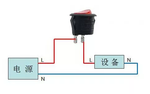
Wiring method of two legged boat type switch
For a two legged boat shaped switch, it is absolutely not allowed to connect one of its two terminals to the positive pole and the other to the negative pole, as this will cause a short circuit.
The correct connection method is that the positive pole of the power supply can enter any terminal of the ship switch, and then be connected to the load through its other terminal before returning to the negative pole of the power supply.
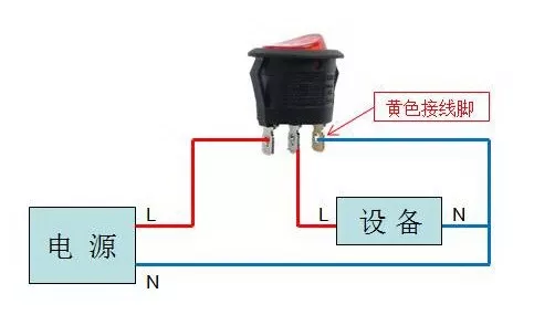
Wiring method of tripod type switch
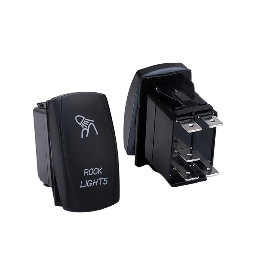
The structure of the three legged boat shaped switch is shown in the figure. The middle foot is the common point of com, and one on both sides is the NC (normally closed) point and the other is the NO (normally open) point.
When making a conversion switch, the middle is the moving contact and the two sides are the fixed contact;
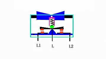
When making a power switch, you can refer to the following diagram and connect a separate neutral wire to pin 3. This way, the light will turn on when the switch is in normally open contact, and the light will not turn on when the switch is in normally closed contact:
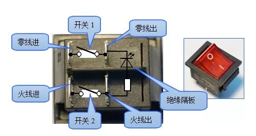
Wiring method of four legged boat type switch
Four legged boat type switches usually come with indicator lights, and wiring can refer to the following diagram:
The above are three typical connection methods for ship type switches, and others will not be listed one by one. Please refer to the instructions for using the parts for details.
In practical use, we can use the resistance mode or diode mode (short-circuit mode) of a multimeter to test the quality of the ship type switch: if the switch is pressed and the corresponding pin does not conduct, it indicates that there is a problem with the switch.
Everyone can take it apart to see if it's a plastic or metal component issue. If it can't be adjusted by themselves, a new switch needs to be replaced to ensure electrical safety and reliability.